
![]()
Designed by: Vassilis Stergiopoulos
Published by: Vassilis Serasidis at 13.Dec.2008
Introduction
You can experiment with Atmega8515 economically and easily. You can construct the following board, buy an AVRISP unit, download from Atmel AVRstudio and you are ready. The circuit is easy and I believe is very useful. Instead of paying a lot of money for evaluation boards or development systems, you can start with this board I have made and the help of an AVR In System Programmer (AVR ISP). This is the way I work. Firstly, I wrote the software and then I burnt the AVR with an ISP. With this board I studied the chaos of timers on ATmega8515 for just a few PWM (Pulse Width Modulation) applications.
If I want another one board, I build it in less than a half an hour.
I think these boards and source codes I give you, will be very useful for people who start their journey to the magic world of AVR microcontrollers.
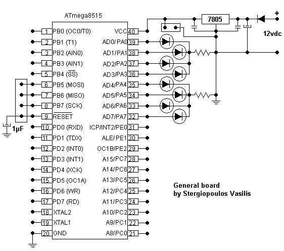
The circuit
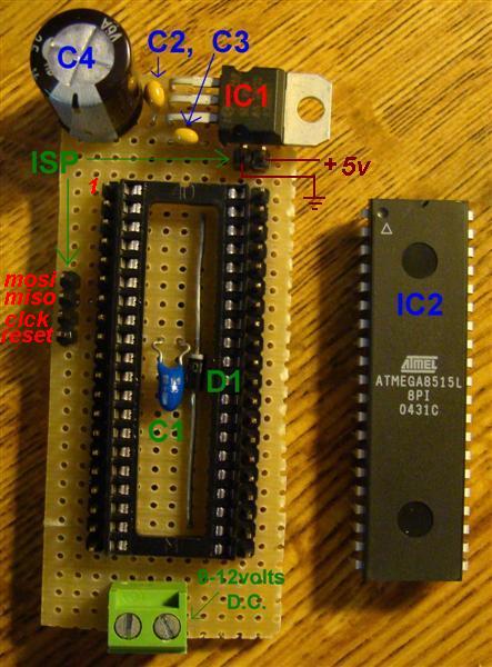
I have placed an electronic stabilization unit with 7805 IC1.
D1 is for protection against wrong connection. C2, C3 are always present for proper operation of IC1.
C4 is for better filtering. The unit is powered with a rectified AC wave of 9Volts.
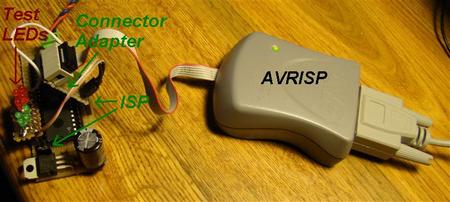
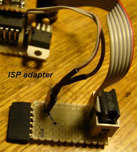
There are 6 pins for ISP (In Circuit Programming) where you can connect the AVRISP. For simplicity the connector is split in two. You can easily build an adaptor for ISP connector as shown below.
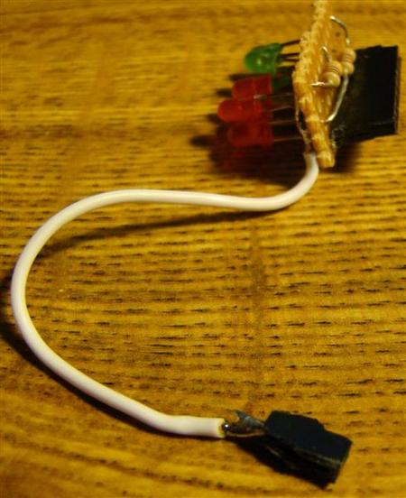
You can write a test program and directly test it on this board. I have placed pins at every pin, so I can connect any additional components with an additional board, like the test leds shown.
I have also two test programs where we can see some interesting simple uses of the timer TC0 of the unit.
In the examples I give an example of interrupt. You can see a way of varying the intensity of a LED.
Components list
IC1: 7805
IC2: ATmega8515
C1: 1�F
C2=C3: 10 nF
C4: 1000
D1: 1N4001
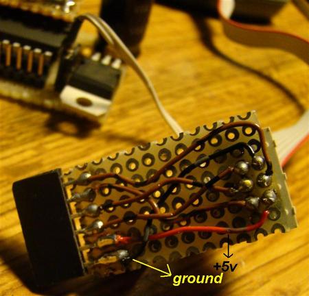
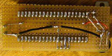
The back side of the board, showing the connections.
Below the ISP adapter is shown. This way the final pcb is significantly simplified that using a 2x3 pins array.
Also a simple LEDs array that can be plagued easily to the pins. The common is connected to ground with separate pin (white wire)
|
|
|
|
; ==================== Example no1 (in Assembly) ==================== ; Test timers in ATmega8515 ; every time that tc0 produces a match interrupt the counter cnt ; is incremented and output to portA. ; The square wave is present at pin no1 (B0) .NOLIST .INCLUDE "m8515def.inc" .LIST .def .def .def .def .def .def
; Code starts here .CSEG .ORG $0000
; Reset- and Interrupt-vectors rjmp rjmp rjmp rjmp rjmp rjmp rjmp rjmp rjmp rjmp rjmp rjmp rjmp rjmp rjmp rjmp rjmp
; ************** Interrupt service routines ******** IInt0: IInt1: TCpt1: TCmp1: TCmp2: TOvf1: TOvf0: SrTrC: URxCp: UTxDe: UTxCp: AnaCp: XINT2: ; In Extended MCU Interrupt Register EMCUIR ; bit0: ISC2: Interrupt Sense Control 2 ; If ISC2=0 then the falling edge of INT2 generates the interrupt ; Provided that I-flag=1 in SREG and in bit5=INTF2=1 (interrupt-enable bit) in GICR. TCMch: EERdy: SPRdy: ; **************** End of interrupt service routines ***********
; ---------------------------------------------------------------------------------- ; Timers notes ; T/C0 output OC0: pin1 ; TCCR0 Timer/Counter Control register ; Bit7 = FOC0 = 0 in fast PWM mode ; Fast PWM: (bit6=WGM00, bit3=WGM01) = (1,1) = FAST pwm MODE ; clock select ; bits
2,1,0 = cs02, cs01, cs0 ; ; ; ; ; ; ; (bit5,bit4)=(com01,com00)=(1,0) non-inverting mode oc0=0 on match and oc0=1 on bottom. ; so TCCR0 = 0110 1101 = $6d ; TIMSK Timer Interrupt Mask Register: set bit0 = Output Compare Match Interrupt Enable = OCIE0 ; TIFR Timer Interrupt Flag Register: bit0 = ocf0 = Output Compare Flag 0 goes 1 when match occurs ; ; ******************** Main program ********************************
main: ldi
loop: |
|
; ==================== Example2: (in Assembly) ====================
; Test timers in ATmega8515 ; The pwm is changing it's duty cycle between 0 anf 255 and output to pin1 (B0) ; The duty cycle value is stored in register "pwm". ; The pwm is counting increasing and when it reaches 255 it .NOLIST .INCLUDE "m8515def.inc" .LIST .def .def
; Code starts here .CSEG .ORG $0000
; Reset- and Interrupt-vectors rjmp rjmp rjmp rjmp rjmp rjmp rjmp rjmp rjmp rjmp rjmp rjmp rjmp rjmp rjmp rjmp rjmp
; ************** Interrupt service routines ******** IInt0: IInt1: TCpt1: TCmp1: TCmp2: TOvf1: TOvf0: SrTrC: URxCp: UTxDe: UTxCp: AnaCp: XINT2: ; In Extended MCU Interrupt Register EMCUIR ; bit0: ISC2: Interrupt Sense Control 2 ; If ISC2=0 then the falling edge of INT2 generates the interrupt ; Provided that I-flag=1 in SREG and in bit5=INTF2=1 (interrupt-enable bit) in GICR. TCMch: tcm: tcm1: tcm2: EERdy: SPRdy: ; **************** End of interrupt service routines ***********
; ---------------------------------------------------------------------------------- ; Timers notes ; T/C0 output OC0: pin1 ; TCCR0 Timer/Counter Control register ; Bit7 = FOC0 = 0 in fast PWM mode ; Fast PWM: (bit6=WGM00, bit3=WGM01) = (1,1) = FAST pwm MODE ; clock select ; bits
2,1,0 = cs02, cs01, cs0 ; ; ; ; ; ; ; (bit5,bit4)=(com01,com00)=(1,0) non-inverting mode oc0=0 on match and oc0=1 on ; bottom. ; TIMSK Timer Interrupt Mask Register: set bit0 = Output Compare Match Interrupt ; Enable = OCIE0 ; TIFR Timer Interrupt Flag Register: bit0 = ocf0 = Output Compare Flag 0 goes 1 ; when match occurs ; ; ******************** Main program ********************************
main:
loop: |
|
|
Download the source code in assembly, schematic and pictures of this project |
Created by Vassilis Stergiolpoulos and published by Vassilis Serasidis at 13.Dec.2008