

Designed and published by Serasidis Vasilis
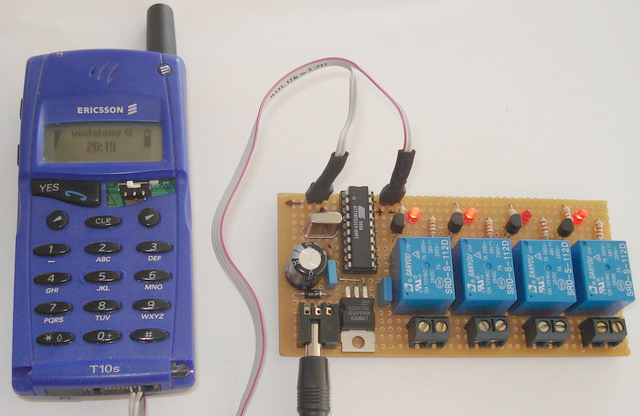
>> Photo of a workable <SMS remote control> with 4 relays version.
Introduction
With this circuit we can control up to 8 devices (4 devices in our example project), by sending a specific SMS message with any mobile phone. It's very useful in the case that, at the place we have the devices, we have not a wired (fixed) telephone line. If you have an old ericsson mobile phone and you are not using it, its the time to build some useful with that. The controlling that we can do to the devices, it is ON , OFF or Reset.
Usage of this circuit
With this circuit you can switch-ON , OFF or Restart some Linux servers, ADSL modems, Printers, Door with electric lock, Garage door, House lights, Water pumps, electric sunshade, Block the engine of your car or your motorcycle, at the steal case and much more. The purpose of this circuit is to make the human life better and easier.
The circuit
The hardware of the circuit is very simple, because the communication port of ericsson mobile works at the 5 volts with AT commands ( like the modem commands, but for mobile phones).
The firmware of the AT90S2313 (or ATtiny2313) is very complicated because, we have to convert the 'septets' of the phone into 'octets' because the AVR needs bytes with 8 bits length ( The 'septet' is 1 byte with 7 bits length and 'octet' is 1 byte with 8 bits length). All this process is necessary for decoding the text message from the SMS.
|
This circuit is working on both AT90S2313 and ATtiny2313 microcontrollers. In case of ATtiny2313 you have to select "External Crystal Oscillator" instead of default "internal RC oscillator" from the "Fuses" tab of your programmer's software. You have to uncheck the "Divide clock by 8 internally". |
>> Schematic of SMS remote control circuit.
When you finish the circuit connect it to the mobile phone, turn on the phone and then power on the circuit, not before . The AVR will try to read the message from the 1st memory location of the phone, for that I suggest you to delete all SMS messages from the phone before you connect it to the circuit. If there is no message to the 1st memory location, the AVR is trying again until you sent any.
The format of the message must be only '1' or '0'. '1' to enable, or '0' to disable the device. The message must have only 8 numbers, '1' or '0' , alone or mixed .
Example: if you send the message 11000100 then you enable, starting from the right, the devices 3,7,8 ('1') and disabling the devices 1,2,4,5,6 ('0') .
If you want to send a new message and you don't want to change some device, must send the same number as the old message.
Example: If you want to enable only the 5th device, you must send a new message like 11010100 to keep the other devices as there are (we send the same message as the old ( 11000100 ) and we change only the 5th bit from '0' to '1' to enable the device ).
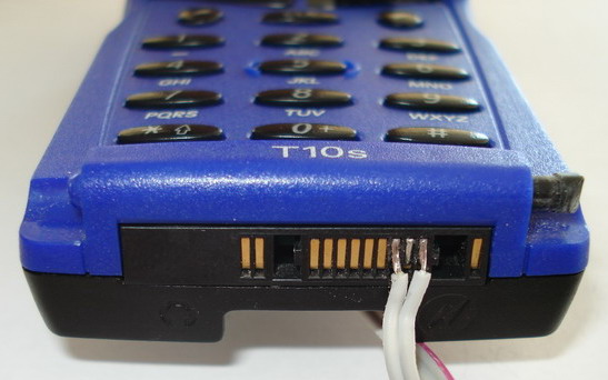
>> You don't need any Data cable. Connect the AVR's pins direct to T10s connector.
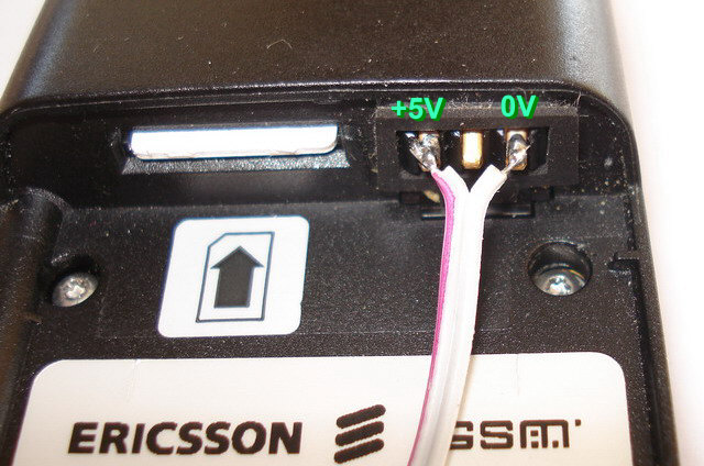
>> You don't need any battery for T10s. Take +5V DC from <SMS remote control> board.
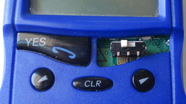
>> You can remove the <NO> key from T10s and solder an ON-OFF switch in this place. If you put it in ON position, the phone is will power-ON automatically every time you cut and then apply again the main +12V DC power supply. To add this switch you have to disassemble the T10s.
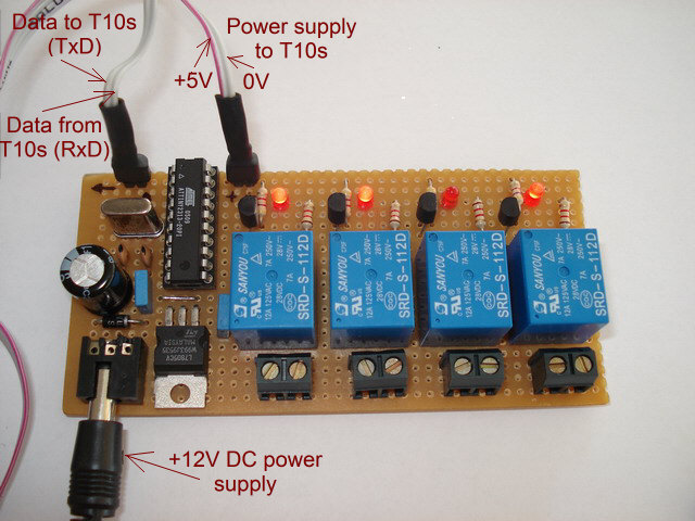
>> The <SMS remote control> board (4 relays version).
>> The PDU decode proccess. Take 7 bytes (8bits) and convert them to 8 bytes (8bits) by adding one zero at the start of each byte. The PDU format uses bytes with 7bit length.
Advice !
If you want to protect your devices from other person's messages, modify the source code, to read the AVR, your telephone number before execute any message. In the source code I have some part of code, to read the telephone number, the service center number, the date and the time of the received message.
The project its based on the Greek mobile phone network of <Vodafon GR> and i don't know if the SMS message in other country, have the same syntax ( I mean the form of the septets that the GSM receiving from the GSM network ).
After the GSM receive the message, the AVR execute it, delete it from the phone memory, to release the 1st memory location and starts again the searching for a new incoming SMS message.
Service mode
If you connect the pin7 (PD3) of the AVR to MAX 232 chip and this to computer, you will see at the terminal window software, all the data that the GSM sends to the AVR (Sender's number, service center number, date, time and the AT commands ) . Setup the COM port to 19200 bps 8n1.
Troubleshoot
I have test it only with Greek sim cards and T10s mobile phone. I don't know if this circuit works fine to other cell phone providers in other countries or other mobile phone models. You can build the optional diagnostic circuit that is in the dot frame of the schematic, and to connect the circuit with PC via RS232 port.
When you power-on the circuit and the phone, the AVR will send the following commands to the mobile phone:
1) AT+CPMS="ME" (Select the phone memory "ME")
and
2) AT+CMGR=1 (read the received message from memory position 1)
If the mobile phone will response with:
AT+CMGR=1[CR][CR][LF] (this message is sent when there is no message in the phone memory)
+CMS ERROR: 500[CR][LF]
On this case the AVR will send again the commands 1 & 2
If the mobile phone will response with:
AT+CMGR=1[CR][CR][LF] (this message is sent when a new message arrives in the phone memory)
+CMGR: 0,,26[CR][LF]
0791039624910000240C91xxxxxxxxxxxx00003001205151302108B1180C068BC162[CR][LF]
OK[CR][LF]
(xxxxxxxxxxxx is the phone number of the sender)
the AVR will decode the septets message to octets, execute it (arm or disarm the relays) and send the command
AT+CMGD=1 (delete the received message from memory position 1)
to delete the message from the phone memory.
You can see the voltage of the PortB with any voltmeter if you have +5 or 0v voltage, to check if the command you send, for example"11001010", is executed.
History of SMS remote control (SMSrc):
03.12.2006
V2.2
24.08.2006
V2.1
The command method has not change it, you must send only up to 8 numbers '1' , '0' , 'r' and 'R' . For example 110r101R .
06.07.2004
V2.0 is now available. I have re-write the code again from the beginning and I add 2 more features
The new code is more stable than the old one. The command method has not change it, you must send only 8 numbers '1' or '0' for example 11001010 .
23.10.2002
V1.0 is now available. You can control up to 8 devices by sending commands '1' or '0' . Example: 11011010
Downloads
|
|
Download the source code and hex file of SMSremote control v2.2 |
|
|
Download the source code and hex file of SMSremote control v2.1 |
|
|
Download the source code and hex file of SMSremote control v2.0 |
|
|
Download a small improved version of SMS remote controller with source code and the Hex files of project sms_controller.zip v1.01 |
|
|
Download the schematic, source code and the Hex files of SMS remote controller project smscontroller.zip v1.0 |
Learn more about the Ericsson AT commands with ericsson T28 _R1A.zip file.
The pduspy.exe is a software that allows you to control the SMS memory of the smartcard or the SMS memory of the ericsson mobile phone via RS232 serial port of PC computer. For that, you need to buy (or to build your own) one data-cable to connect the phone with PC computer.
Updated at 24.08.2006 by Serasidis Vasilis