![]()
|
RF Transmitter |
RF Receiver |
Introduction
How many times you needed some remote control to handle some electric device ? Many times. There are lot of remote controls like infrared, RF, SMS (like my other circuit) and more. The basic small-range remote controls are 2, Infrared and RF (Radio Frequency). One of the weaks of Infrared is that the signal can not pass the walls. So, if you want to control your garage door, the only way is to use some RF remote control. The circuit (transmitter and receiver) uses few components and ordinary (I love few component circuits) . It's easy to be built because you don't have to tune-up any coil or variable capacitor. The RF modules are fix to work in 418MHz area.
I have designed this remote control considering :
a.) the verification of the received data because many other devices are working in this frequency (418MHz)
b.) and the power-saving of the transmitter. A transmitter must have long battery life. It's not the best choice for you to change the battery every 3 days ;) . I don't care about the receiver`s power supply, because receiver must be working all the time.
Features
|
Transmitter
|
Receiver
|
Transmitter description
![]()
Schematic of the transmitter
The transmitter is constituted by AT90S2323 microcontroller and TLP-418A RF transmitter module that works at 418MHz. I have designed the transmitter for more battery conservation and safe transmission of the data.
example: if byte1=30h, byte2=35h and byte3=02h the 4th byte (chechsum) will be (byte1) XOR (byte2) XOR (byte3) = 30h XOR 35h XOR 03h = 06h.
This method use 4 bytes x 8 bit each = 32 bit length (without start and stop bits). That is mean 1 possibility at 4.294.967.295 to receive the receiver, the same 4 bytes from some other RF device.
This transmitter works with all AT90s2323 chips but better is AT90LS2323 with working voltage 2.7 - 6 volts. The microcontroller that I use is AT90S2323 with working voltage 4 - 6 volts. Its worked fine with 3v lithium battery.
If you press the S2 key, the logic of this pin goes to '0' (0V) and AVR awake from the sleep mode (because PB1 is INT0) and check if pressed the S1 key. If not, the AVR take as pressed key the S2. If yes the AVR take as pressed key the S1.
If you press the S1 key the logic of this pin and PB1 (through 1N4148) goes to '0' (0V). In this case the AVR gets as pressed key the S1.
Then, it calculates the checksum and transmits 4 times the same 4 byte sequence to make sure that receiver will take the data and goes to sleep mode until next interrupt on PB1 pin.
When the INT0 pin (PB1) of AVR goes to 0V, the transmitter TLP-418A works. If you stop pressing the switch S1 or S2, the TLP will stop work.
As antenna you can use ~7 cm cable in to transmitter`s box.
TIP!
You can use the TLP-434A transmitter with RLP-434A receiver instead of TLP-418A and RLP-418A. The only difference is that TLP-418A and RLP-418A work on 418MHz and TLP 434A and RLP-434A work on 433.92 MHz . The microcontroller hex code works on both models (418A or 434A).
Remeber to use the same frequency modules. For example, use the TLP-418A transmitter with RLP-418A receiver OR use the TLP-434A transmitter with RLP-434A receiver.
Receiver description
Schematic of the receiver
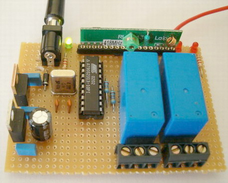
The receiver is constituted by RF receiver module RLP-418A at 418MHz, the microcontroller AT90S2313 and the 2 relays which can handle any electric (or electronic) device up to 10 Amps (the contacts of my relays are 10Amp at 250Volts).
The RLP-418A is an RF receiver module that works at 418MHz with ASK modulation. There are 2 outputs from this module, the digital, with levels from 0v to VCC (5 volts in our case) and the analog output. Analog output is not used. The transmitter sends 4 bytes with 2400 bps 4 times and the receiver RLP-434A, collect them and move them to AT90S2313 through RxD pin, PD0.
Two reasons to select AT90S2313 (20pins) instead of AT90S2343 (8pins) is because
a.) AT90S2313 uses a hardware UART adjusted at 2400bps and the hardware UART is more stable, with smaller code, than software UART that I use in the transmitter. If some serial data arrives in the middle-time of some other routine other than receive routine, we will loose these bits of data for sure. The hardware UART does not have this problem because has hardware buffer for this function (UDR register). This is what I mean when I say that the hardware UART is "stable".
b.) with AT90S2313 we can drive up to 14 relays with future upgrade of the firmware, one relay to each pin.
As antenna you can use a cable 30 - 35cm long
The power supply
The power supply of receiver
The power supply of the RF receiver is constituted by 2 voltage regulator, LM7812 and LM7805. The first one (12V) is only for powering the 2 relays and the 2nd (5V) for powering the AVR microcontroller and the RF receiver module. The LED, is a voltage indicator and the 4 capacitors are for flattening the voltage.
Usage of transmitter
Power on the receiver and press S1 key on the transmitter. You will see that the relay on PB0 of the receiver will be armed. If you press one more time the same key, the relay will be disarmed. If you press S2 key from transmitter you will see that relay on PB1 of receiver will be armed. If you press one more time the same key, the relay will be disarmed. Each key is for 1 relay only.
I choose to drive 2 relays and not only 1 because for some application like garage door 1 relay can handle the door (open-close) and the other to turn-on or off the light of the garage.
UPDATED
New feature added! roll-code. Roll-code function is increasing the security of the remote control system, because it changes the transmitting code every time you press any key on the remote control (AT90S2323 circuit) and the RF thief scanners will be useless!
|
|
Click here to download the firmware, source code and schematic for AT90S2313 and AT90S2323 microcontrollers |
The RF modules TLP-418A and RLP-418A are manufactured by Laipac
T
(c) 04.10.2004 by Serasidis Vasilis
Updated 24.07.2005