Designed: September 2009 by Antonios Theodosiou.
Published: 25.Nov.2010 by Vassilis Serasidis .
The source code was written in AVR C language.
|
|

Intro
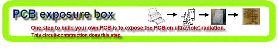
Tired of spending hours and hours in wire soldering? Do your circuits look ugly and you are looking for a way to produce professional-like PCBs? Then you had better try photoetching. And the first step to do that is to have the right equipment that is an Automated Exposure Box. Moreover if you like tinkering with microcontrollers, here is the challenge and it's high time you launched the design of your own PCB Exposure Box.
In the following lines I describe theprocedure I followed to build the Box, the Lamp System and the Countdown System which is based on the AVR mega8 microcontroller.
Brief Description
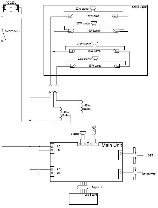
Four blacklight lamps, 15W each, emit radiation at the region of UVA, with a peak around 350nm where the thin surface above the copper of the photosensitive board, is... sensitive. The lamps are taken by two and are connected in series thus shaping two similar modules. Each module has its own ballast and can be connected to 220V AC via a relay.
A microcontroller counts a user defined countdown and upon reaching zero activates a relay. The time remaining is displayed on four 7-segment led displays. The maximum countdown is 99 minutes and 59 secs.
The desired countdown is entered using only two buttons, SET and START/STOP. Short term push of the SET button will increase the current digit while prolonged push will change the digit from secondss to decades of seconds, to minutes and so on. Pushing once the START/STOP button, will make the MCU accept the desired countdown. Pushing the START/STOP button one more time, will start the countdown and connect the lamp system to 220V AC, via the relay. If START/STOP button is pushed again before countdown reaches zero, the lamp system will be deactivated. When the countdown reaches zero the lamp system is deactivated and a 3 seconds beep is sounded. The timer remembers the last used countdown and uses it as default every time the system is switched on.
All things above are housed in a wooden box. You can design the box by yourself however I had it done by a technician.
There are 3 distinctive parts that constitute your PCB Exposure Box; the Box the Lamp System and the Counter System along with the display.
The Box
You are gonna need a wooden box with dimensions aproximately 50x30x60 cm3. The box must have an extra room for hosting the countdown board and the two ballasts. The height of that room, that is the distance between the bottom of the box and the shelf, can be 5-8 cm. On the one side of the shelf will be installed the four starter bases and on the other side the four lamps along with their G13 bases.
|
|
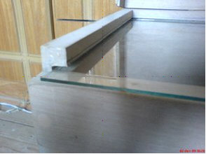
On the top of the box, a clear glass must be attached. I did it as the image shows. Here there is a very detailed description on how to build your own box, upon which I relied to decide the dimensions of my box. However the final design I used is the same as Papanikolaou's box in his Darkroom Timer project. Many thanks to both of them! |
The Lamp System
For the lamp system you will need:
-
4 x 15W Black Light UVA fluorescent lamps with a peak of radiation at ~350nm. Those lamps are suitable for photochemical procedures and can usually be used in insect killing. Examples are F15W/T8/BL from Syllvania and Actinic BL from Phillips
(approx. cost 10�/lamp)
-
2 x 40W Ballast. This is the common ballasts used in fluorescent lamps (approx. cost 2�/ballast)
-
4 x Starters that can support 15W lamps
(ex 22W starters approx. cost 0.5�/starter)
-
4 x Starter bases
(approx. cost < 0.2�/base)
-
8 x Bases for the lamps with holes so they can be screwed on the wood (approx. cost 0.6�/base)
-
Wire. Prefer flexible wire which is commonly used in fluorescent lamps.
-
20 x Screws. Use the size you thing that best fits.
|
|
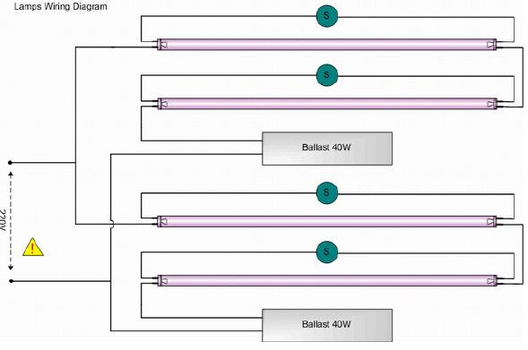
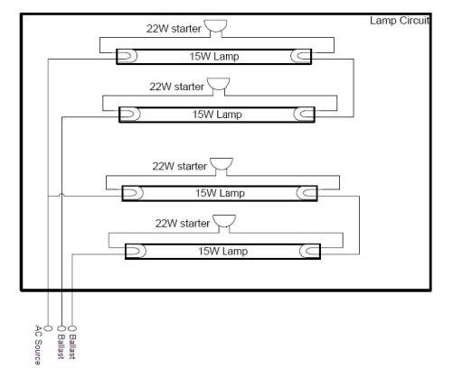
The connections you have to make for the lamps are as in the next image. This is a very popular connection for twolow wattage fluorescent lamps connected in series.
There are twoidentical modules connected in parallel. In each module, initially, the AC current flows through the two starters and the ballast. After a while one of the starters goes open-circuited and the current in the circuit is halted. This brings the ballast inductor in an extremely uncomfortable situation and it reacts violently developing a great voltage across its terminals. The value of the voltage can be as large as some kV and that is exactly what the fluorescent lamps need in order to be turned on. After that transition effect the voltage accross each lamp gets stabillized around the 50~60V which is the lamp�s operation voltage shown in the manuals. |
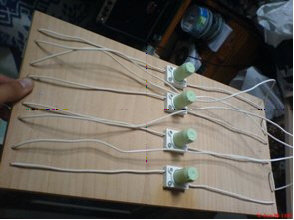
As for the construction details, I put thelamps and the starters on the two sides of the wooden shelf and the two ballasts on the bottom of the box.
|
So, as far as the shelf is concerned I made the following connections.
|
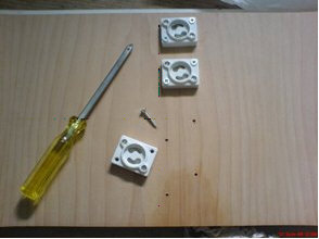
First, I screwed the starters' bases on the one side of the shelf.
|
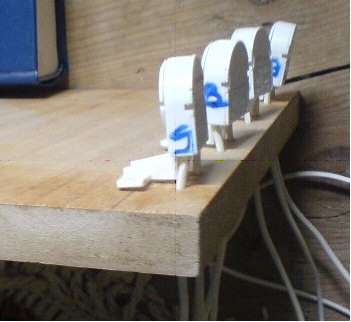
Second,on the other side of the shelf, I screwed the eight G13 lamp holders, having first, drilled the holes needed by the wires to join the lamp bases with the starter bases.
|
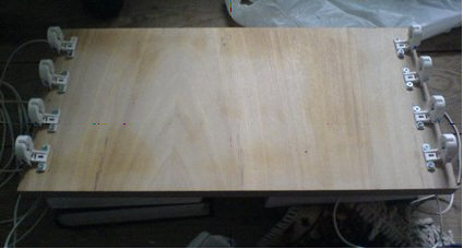
Also don't forget to screw someshelve holders so that you can put and get out the shelf from the box. |
Next, do the wire connections, |
|
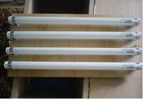
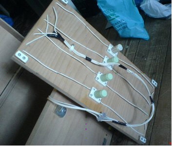
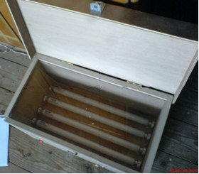
and finish the shelf by populating it with the starters and the lamps |
|
The finished lamp system looks like. |

The Countdown Timer
This is the most amusing part of the story. Here you have to deal with Software and Hardware.
As for the Software part I wrote the code in C using the winAVR and avr-gcc plugin along with avrStudio. Using ProteusVSM I tested the code in simulation environment which saved me a lot of effort and time. Then I downloaded the hex code to the chip with the STK500. I strongly recommend that you try and writethe code by yourself so I don't attach any code here except for the tmrAVR.hex. If you need any help about the code, please mail me at aetheod@hotmail.com.
The schematic of the main unit which contains the microcontroller and the power supply isYou 'll be needing the following components
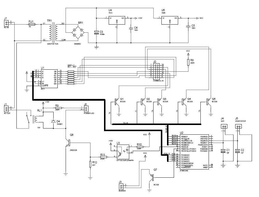
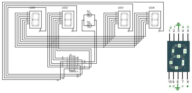
Similarly the led board schematic
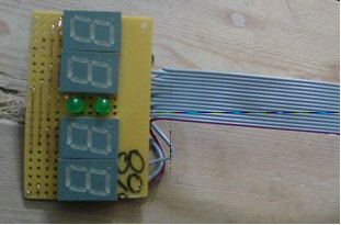
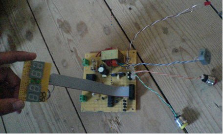
So, after ensuring everything was right it was time to design my last wire-soldered circuit! I started from the led board
|
|
|
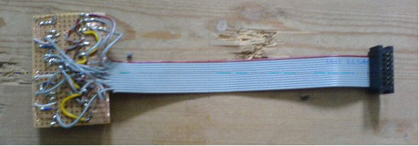
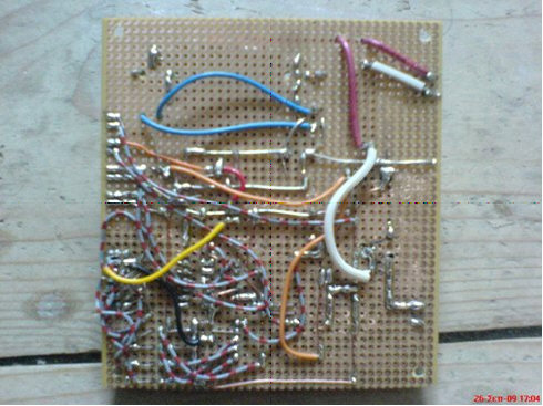
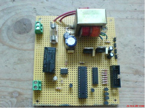
and thecorresponding main unit
 |
|
Connecting the modules together
Putting all together...
So far so good! Everything works fine and it is time to enclose the Lamp System and the Countdown System in the Box. A general diagram helps to identify the place of each module
|
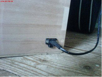
first a socket at the back of the box is installed
|
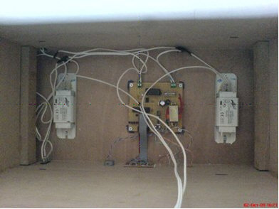
Next, the ballasts, the main board, the led board and the switches.
|
|
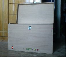
and after the shelf is set ,
|
the PCB Exposure Box is ready.
|
|
|
UVA radiation is harmful and hazardous. Never do you look straight on the lamps. |

PCB_Exposure_BoxPCB_Exposure_Box
![]() Download schematic,source code in C and hex code.
Download schematic,source code in C and hex code.
Published by Vassilis Serasidis at 25.Nov.2010