

Created and published by: Vassilis Serasidis
*** Updated at 12.Aug.2008 by Vassilis Serasidis ***
****** New version added in C language supporting Sony's IR remote controls. Look at the bottom of this page. ******
Introduction
A few time ago I decided to create a media center box to replace my DVD player, sattelite receiver, VCR and my kid's Play Station 2, to one device. So, I made a core 2 duo processor system that actually replaced with succeed, all my electronic devices. The only thing that was missing was a remote control to switch On/Off my Media Center. After I searched on the net to buy a complete remote control system, I saw that the price was a little bit high (about 90 euros). I checked my stuff to find my old 7-in-one remote control that I had bought 2 years ago and I started to build my own remote control receiver circuit.
A second thought...
I focused on ATtiny13 microcontroller because of its small size and its RAM in case I would like to rebuild the source code in C language. After a second thought, I decided to build a completely remote control receiver that it could handle both On/Off and windows or program commands. I searched again on the net and I found an old version of Girder 3.2.9 that was freeware. I went at plug-in settings and I made a few tests to see which plug-in is the easiest to be handled via RS-232 port. I chose the "Creative infra RS232" hardware type under "UIR/IRman/IRA/CTInfra/Hollywood+" plug-in. This plug-in is receiving up to 6 bytes from serial port with 2400 bps (Bits Per Second) making it ideal for my purpose.
The circuit
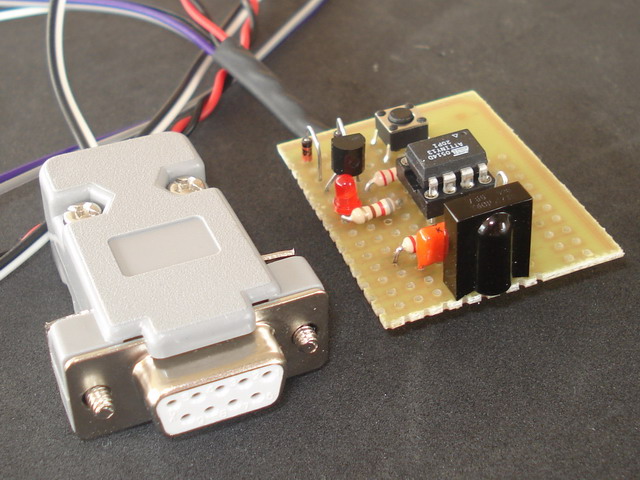
The circuit consists of ordinary components (except of ATtiny13 in some cases). The IC1 is an infrared receiver at 30 kHz. The T2 makes the switch On/Off of Media Center when it gets a High level by IC2. The K2 is connected to the "Power-ON switch" connector of your PC's mainboard (motherboard).
BE CAREFUL!!! NOT THE 220V AC power connector. The two diodes are put to make the connection of K2 to the mainboard, easy. You don't have to worry about which polarity you have to connect this connector to the mainboard. Connect it as you wish. K1 is connected to the power switch (button) of your PC's case. So, you can turn On/Off your media Center with both remote control and your case's power on/off switch. K3 is connected at your RS-232 port of your Media Center. It can work on both real RS-232 ports and USB-to-RS232 converters, in case you haven't got a real RS-232 port.
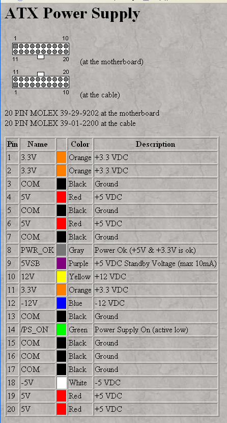
The +5V can be taken by 20pin ATX connector and specific by the pin "+5VSB" (purple cable). The power supply of the circuit must be done by this cable (+5VSB) because it's the only cable that has +5V voltage when the computer is in hibernate, stand-by or power-off mode. The circuit has to be power supplied always for being functional. The ground pin (GND) of the circuit has to be connected with one of the black cables.
At the circuit's photo you cannot see the R4, D3 and C2, because they are included in RS-232 connector's case to reduse the number of the used cables.
Programming the ATtiny13
You can program (burn) the ATtiny13 with IR_ATX_power4.hex file and then go to "fuses" and set the microcontroller at:
"Int. RC Osc. 4.8MHz startup time: 14 CK + 64ms"
Remember!!!
This circuit can work ONLY with RC5 remote controls. If your remote control works with RC6 code, or any other IR (InfraRed) system different than RC5, you will never make this circuit work.
Programming the "Power on/off" key
Select which key of your remote control do you want it to act as "Power On/Off" key. Normally you have to choose the red key that is the most common to power on/off the electronic devices. Press that key continuously and then press the S1 button of the circuit simultaneously with the remote control's key. The red LED will flash. Release the key and S1 both. Now the code of this key has been stored in eeprom. If you want to change the power On/Off key, you have to remake the above proccess and the code of the new key will be stored in the eeprom.
The software
As I said, you can use the Girder 3.2.9 as it is easy-to-use and the last freeware version of this powerful software.
The distribution of Girder 3.2.9 has been stopped from Promixis. I contacted with Promixis to give me the permission to redistribute Girder 3.2.9 from my web site. They told me that redistribution is not allowed and they offered a 2 months demo with a 20% discount in case you buy Girder 5 standard. This offer is for all friends of http://www.serasidis.gr web site. The only thing you have to do is to fill out the "Coupon Code (Optional)" field with this code: GirderPromo09A and click to "Recalculate" button.
A second choice is the "PC remote control v4.213" that can work with my circuit too.
Code for Philips RC5 InfraRed protocol.
--- Added Sony's remote control support. ---
Code for Sony InfraRed protocol.
Created and published at 24.Oct.2007 by Vassilis Serasidis
Updated at 07.Jan.2009 by Vassilis Serasidis